Hydroponic automated System
This page present the hydroponic system installed in fablab verona. Basic material is already present and used, the goal of this project is to integrate automation with sensors and computer and allow growing of plants with less human interaction possible.
This project is an inspiration of an already existing project, Ortocitiy. It is a culture of plants no by hydroponics but classical ground. The characteristic of Ortocity is to be based on LORA technology, it allows a complete autonomy of the system, and monitoring of it far away from first LORA gateway (about 10km).
The LORA technology has been explored, and a LORA gateway has been created to be setup in verona fablab. But this technology isn’t relevant with the hydroponic system since its gonna be used localy at fablab where wifi network is close by and available all the time.
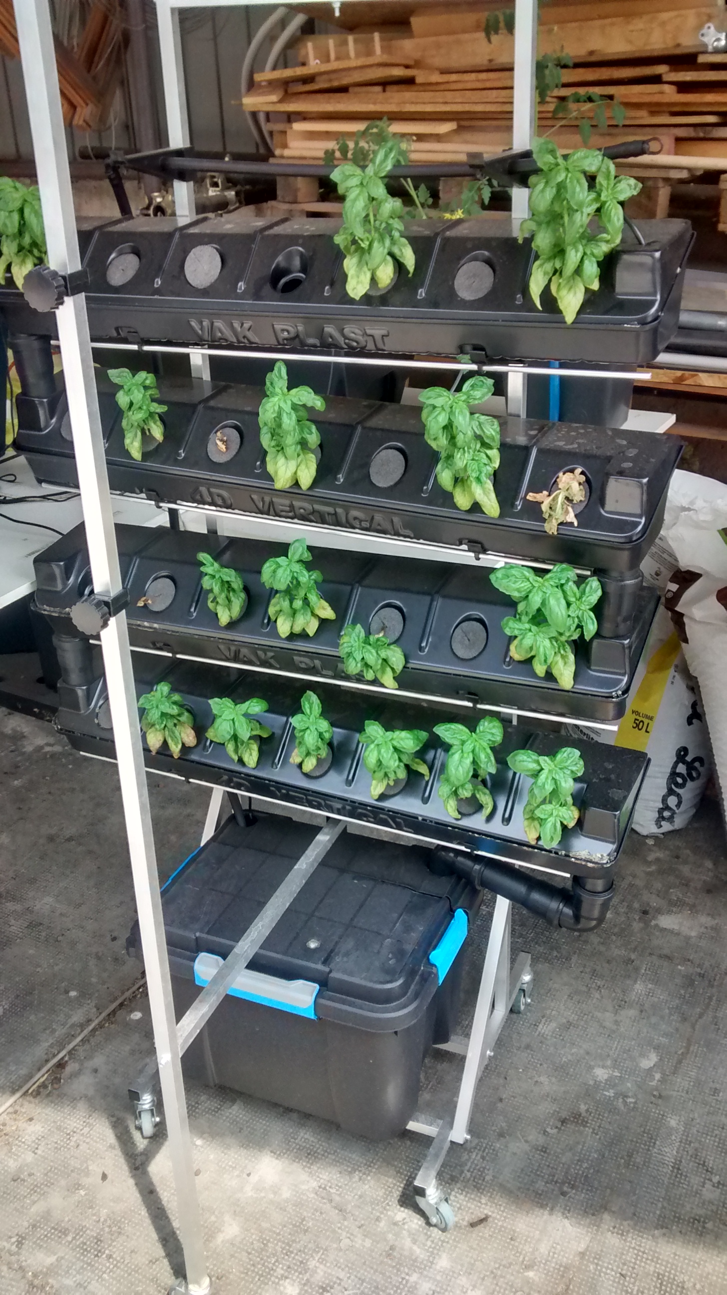
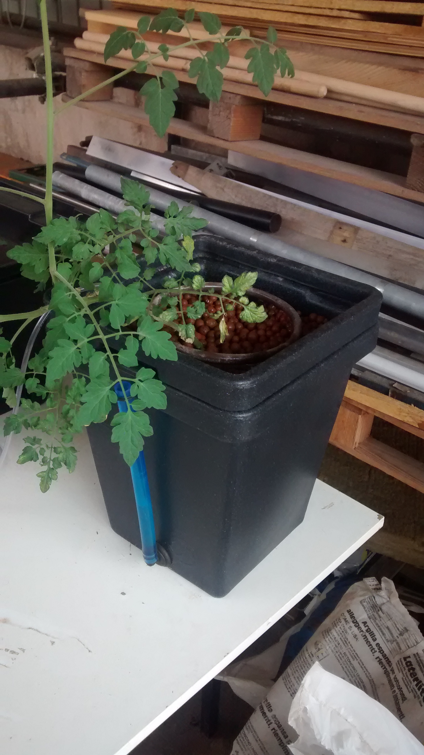
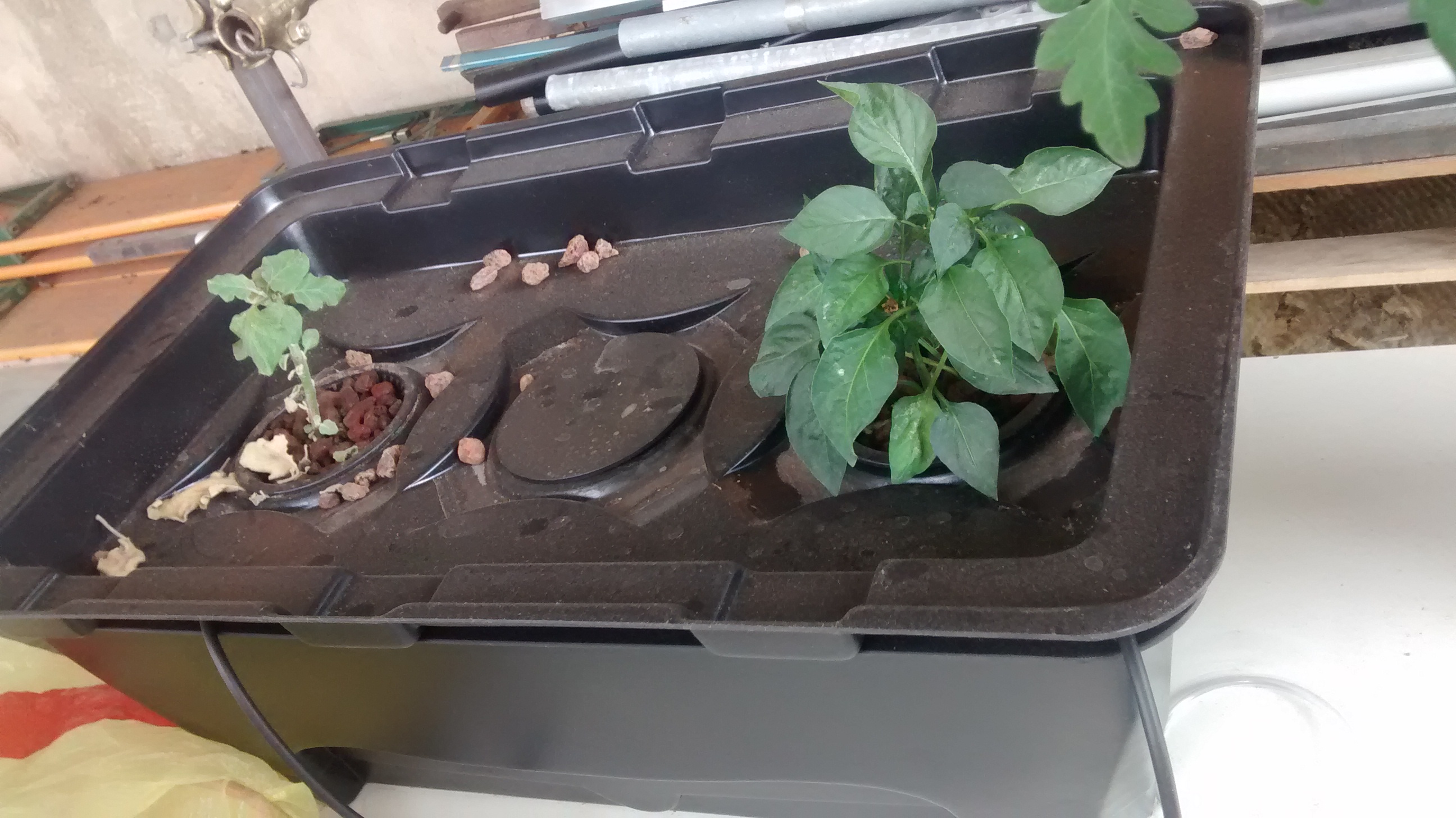
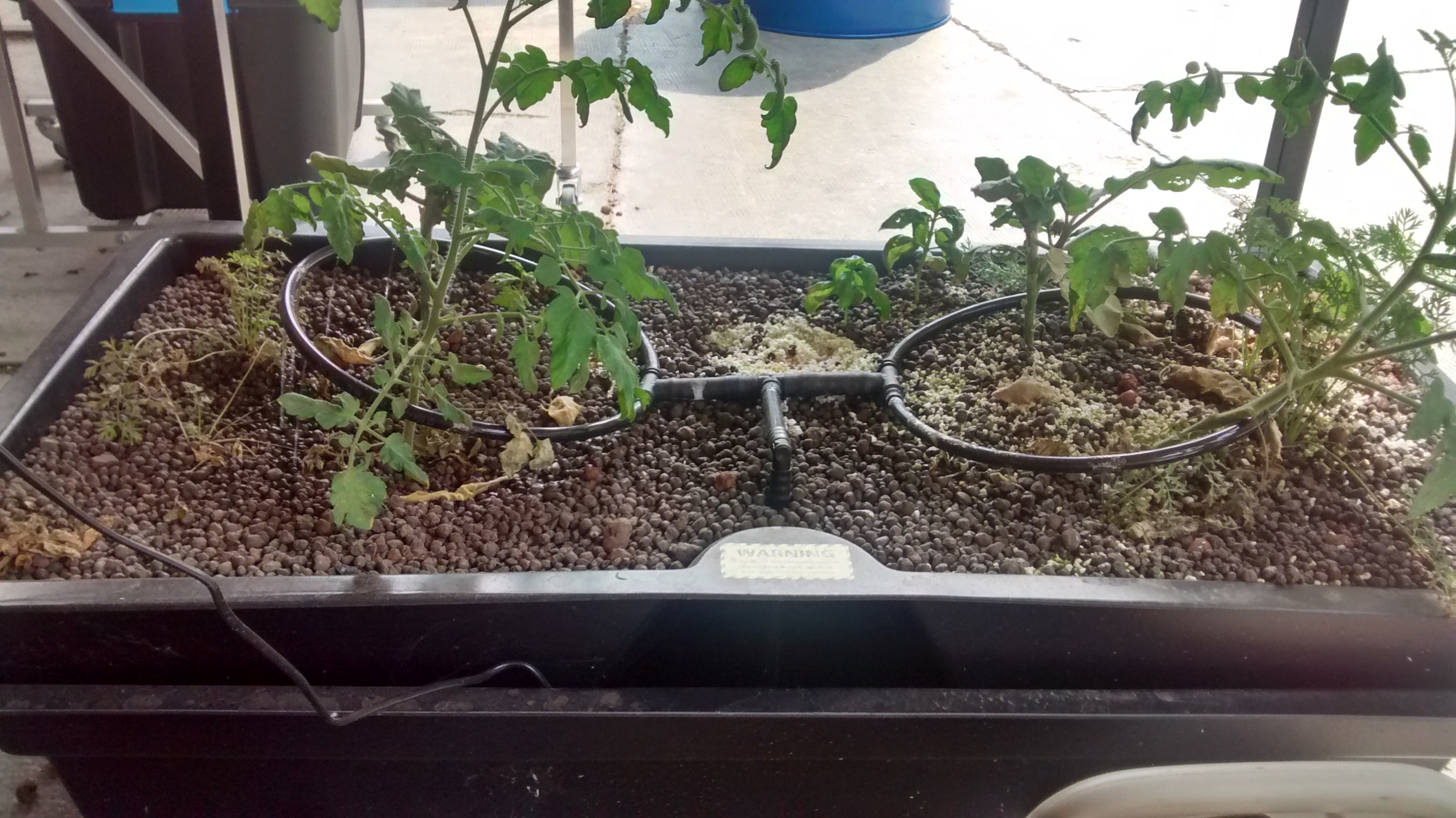
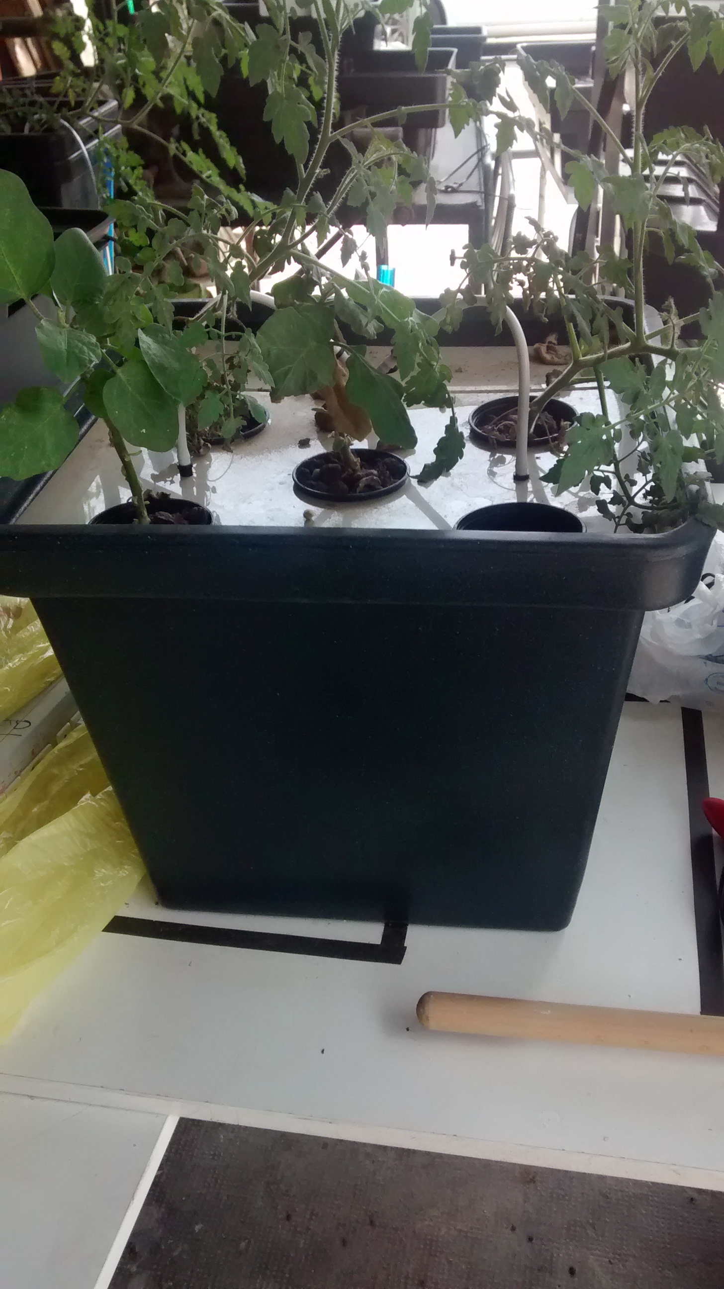
The current material
Several equipment is to be used for this installation, here is the non-exhaustive list :
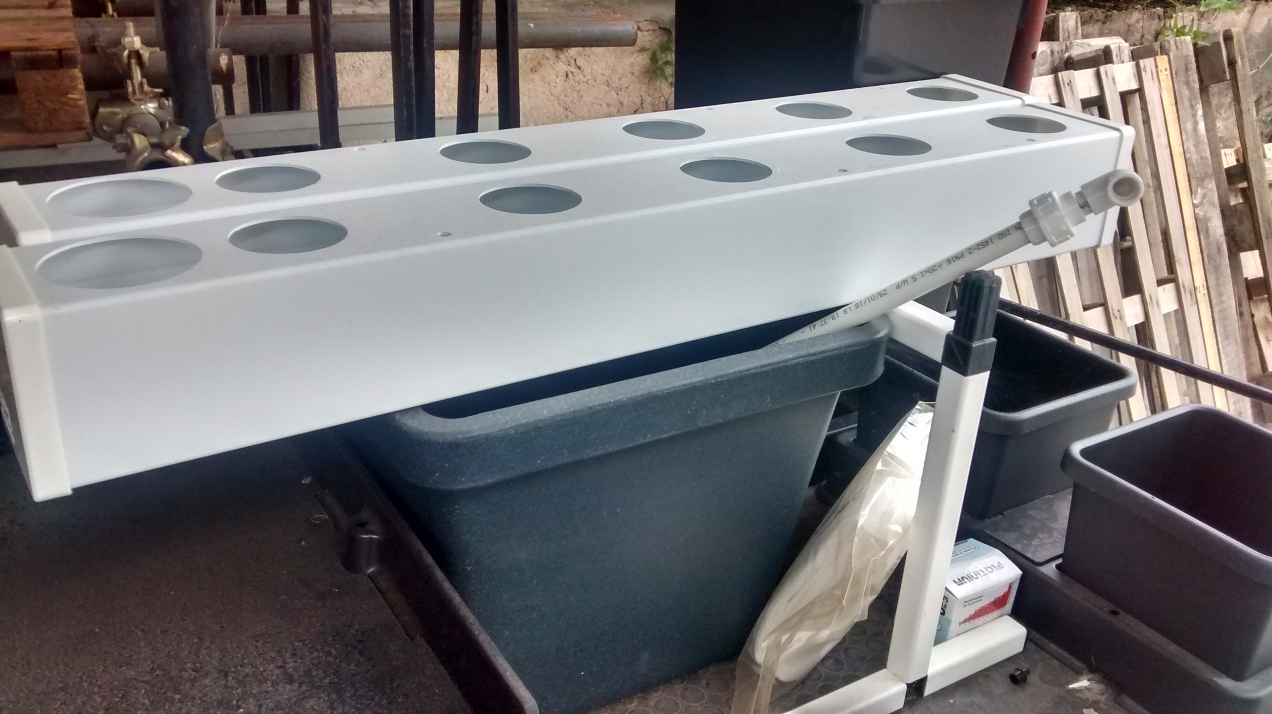
- VERTICAL HYDROPONIC SYSTEM - ONE WALL SMALL - 1SM
http://www.vakplast.cz/home/vertical-hydroponic-system-one-wall-small-1sm-without-light
- 2POT KIT - AUTOPOT
- ATAMI WILMA LARGE 4 VASI 11L
https://www.idroponica.it/sistema-idroponico-wilma-large-4-vasi~23961.html
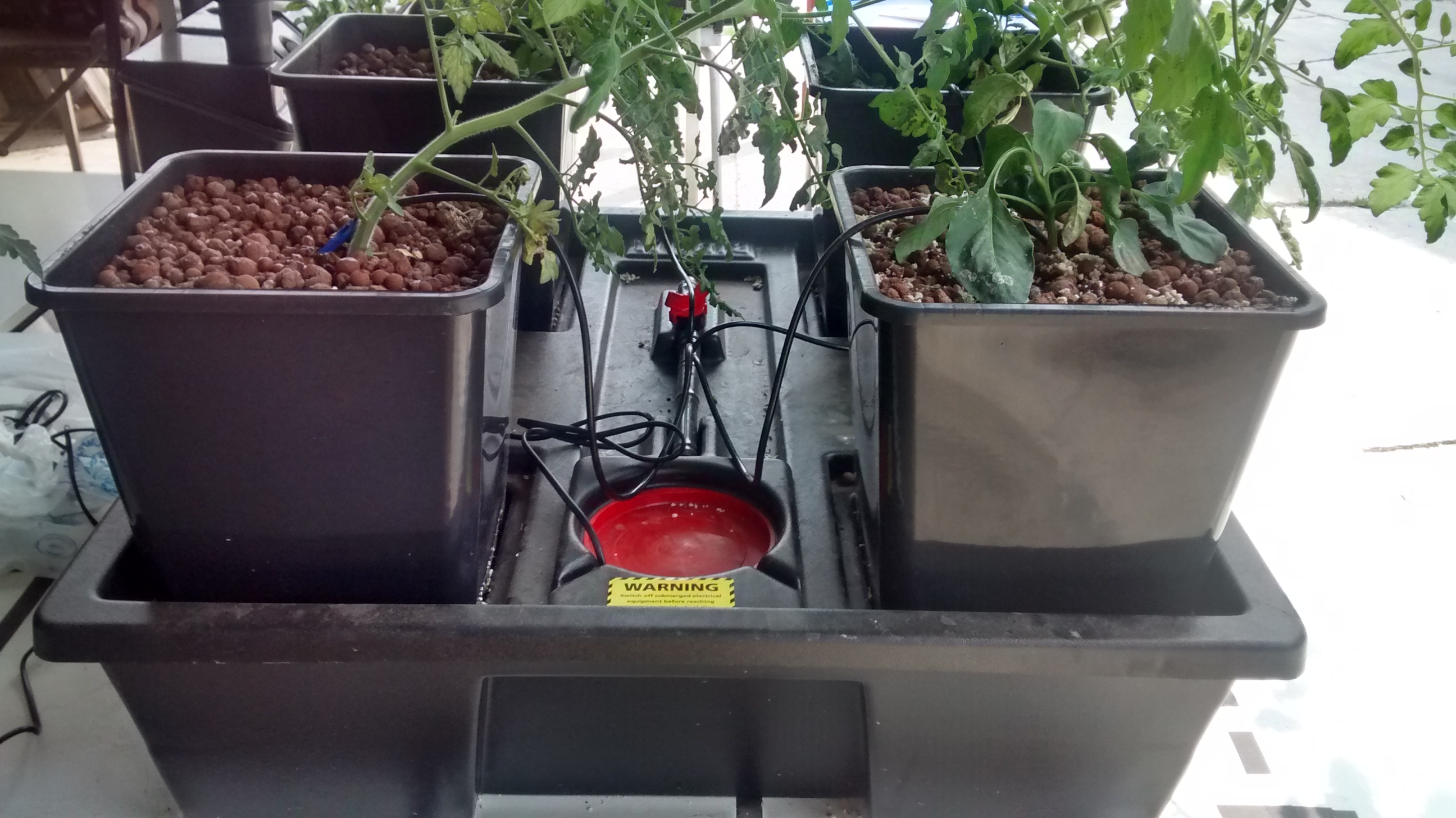
- Water Farm
https://www.idroponica.it/waterfarm-general-hydroponics-ghe~8967.html
- NUTRICULTURE OXYPOT XL - SISTEMA IDROPONICO DWC - 2 PIANTE
https://www.idroponica.it/nutriculture-oxypot-xl-sistema-idroponico-dwc~24848.html
- NUTRICULTURE FLO-GRO 510
https://www.idroponica.it/nutriculture-flogro-510~5104.html
- AEROFARM | SISTEMA AEROPONICO DI GENERAL HYDROPONICS | GHE
https://www.idroponica.it/aerofarm-3-general-hydroponics-ghe~8968.html
- AEROFLO 10 GHE - SISTEMA AEROPONICO
https://www.idroponica.it/aeroflo-10-general-hydroponics-ghe~9196.html
- SISTEMA PLATINIUM NFT NUTRI+ 60
https://www.idroponica.it/sistema-platinium-nft-nutri-60~36786.html
- OCTOGROW NUTRICULTURE COMPLETO DI MODULO ATU
https://www.idroponica.it/octogrow-atu-nutriculture~20692.html
- SISTEMA IDROPONICO PLATINIUM - EBB & FLOW 100
https://www.idroponica.it/sistema-idroponico-platinium-ebb-and-flow-100~23716.html
The solution developped during the residence
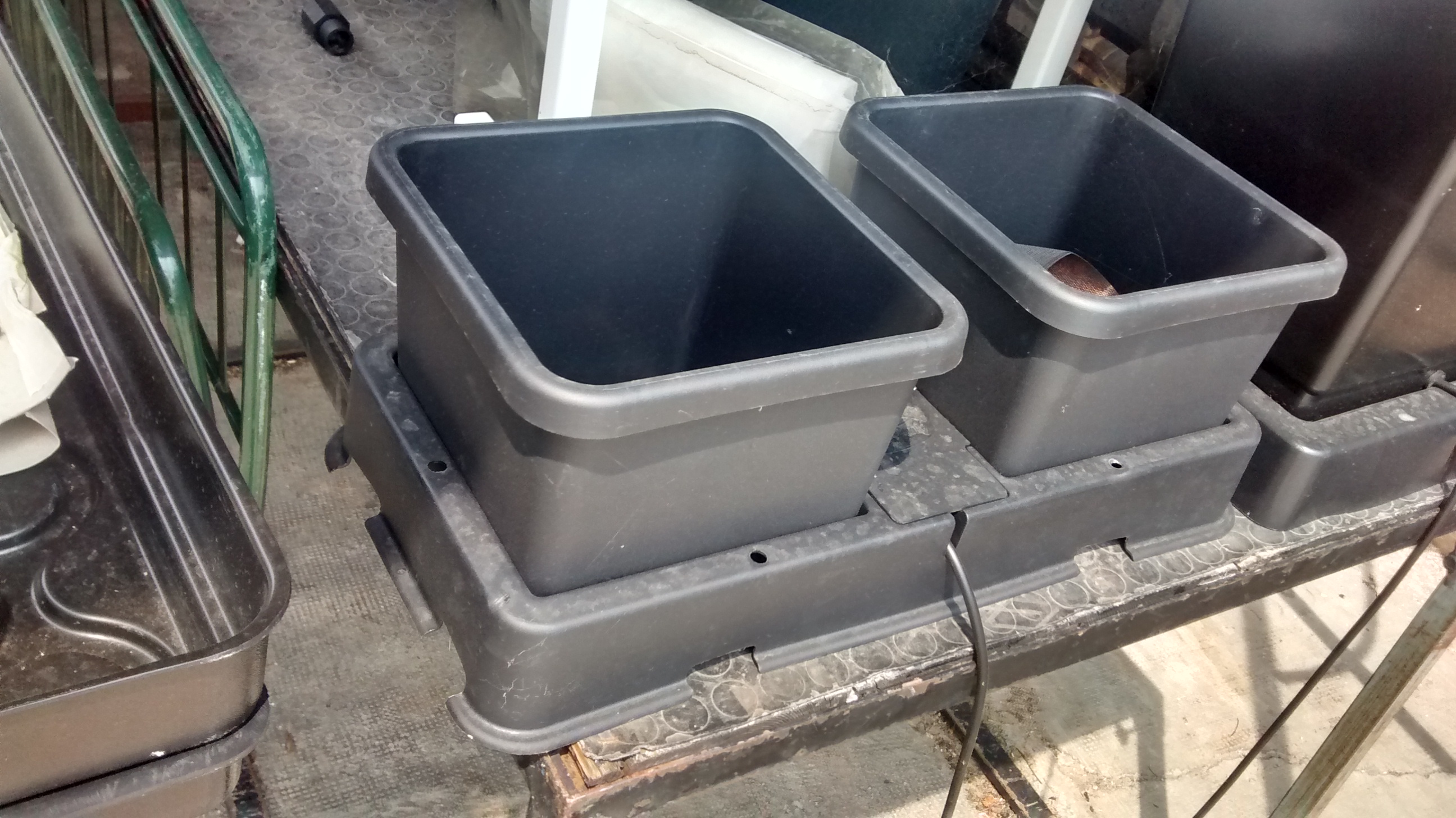
Due to the limited time of the residence, a solution has been developped on only one module, the seed grower.
Solution with MQTT and raspberry pi
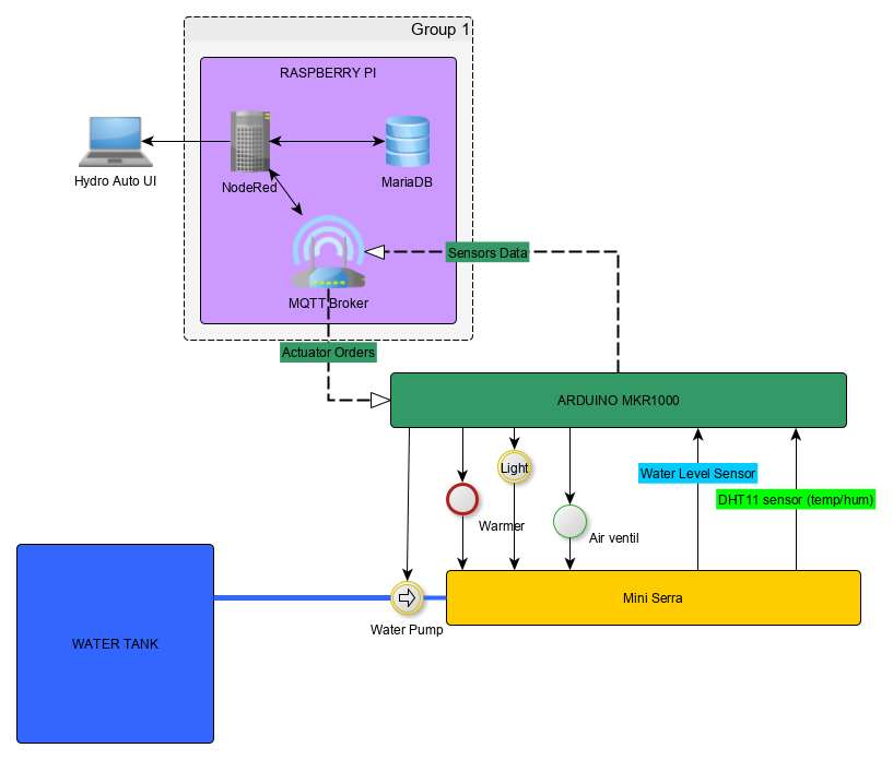
a simple global view of the system with the seed module with what could be different functionnality
Objectives :
Be able to have a full hydroponic system automated by embeded system, monitored and controlled with a user interface.
Requirements:
- Embeded system that control hydroponic installation
- Control temperature
- Monitore humidity
- Monitore Waterlevel
- Independant computer to control data and command embeded System
- Retrieve data from Embeded System
- Store data in database
- Propose User Interface to display data from Database
- Propose User Interface to control Embeded system values
Material used :
For the command and control part :
- raspberry Pi with Raspbian OS, with Node Red & Mosquitto Broker installed
- Arduino MKR1000 connected by wifi to send MQTT messages
- A DHT11 sensor connected to the arduino to get temperature and humidity value
- A custom water level sensor
Schematics
Configuration of the system
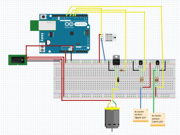
the schematics for the hydro circuits, Arduino MKR is represented by Arduino UNO but pin number are the sames, on the left is the alimentation of the water pump, the small DC engine represent the water pump
Configuration of raspberry pi platform (NodeRed & PHPMyAdmin)
Note
The initial state is to have Debian installed as distribution on the raspberry Pi
Install Mosqito on Raspberry Pi
Mosquitto is the MQTT broker that will allows storing informations on different channels, and exchange of these different information to different devices (a video to present how MQTT [1])
on a terminal
sudo apt-get update
sudo apt-get install mosquitto
sudo apt-get install mosquitto-clients
pip install paho-mqtt
On Raspi, test mosquitto with 2 terminals, one for subscribe a topic, another to publish on a topic
Subscribe to a topic
mosquitto_sub -h 192.168.50.55 -t youtube/test
- mosquitto_sub : subscribe to a topic
- -h : by hostname
- 192.168.50.55 : IP adress of the raspi
- -t : by topic
- youtube/test: topic selected
pbulish on a topic
- -m: message option to publish
- “essai” : message to be published
on the first terminal shall be displayed “essai”
Node Red configuration
NodeRed on raspberry Pi is installed by default on Raspbian distribution. To use GUI of Node red, its needed to install NodeJS on the raspi to be able to install new package, the node red GUI is one of them.
install npm
sudo apt-get install npm
- Launch Node Red via graphic interface or via “node-red-start” command line
- On Node-red interface, go to Manage Palette from the NodeRed menu
- there select to install Node-Red Dashboard package, this will allow to use Node red dashboard nodes
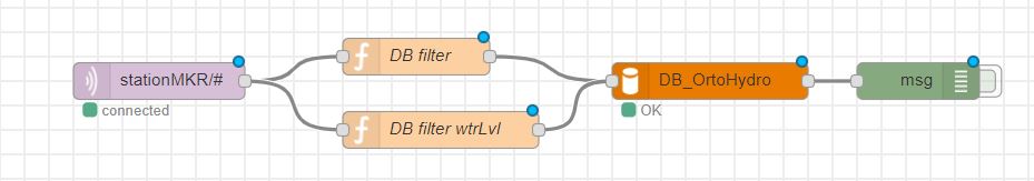
the part of the flow to retrieve and store in database data from DHT11 & water level sensor
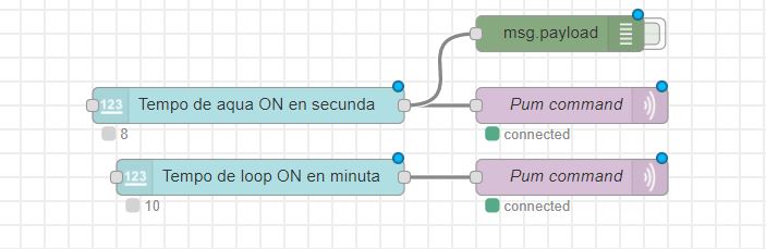
the part of the flow to command to Arduino about timing on the water pump and the period to be used by arduino to measure temperature and humidity
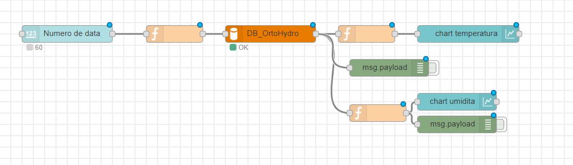
the part of the flow to display interface of the system
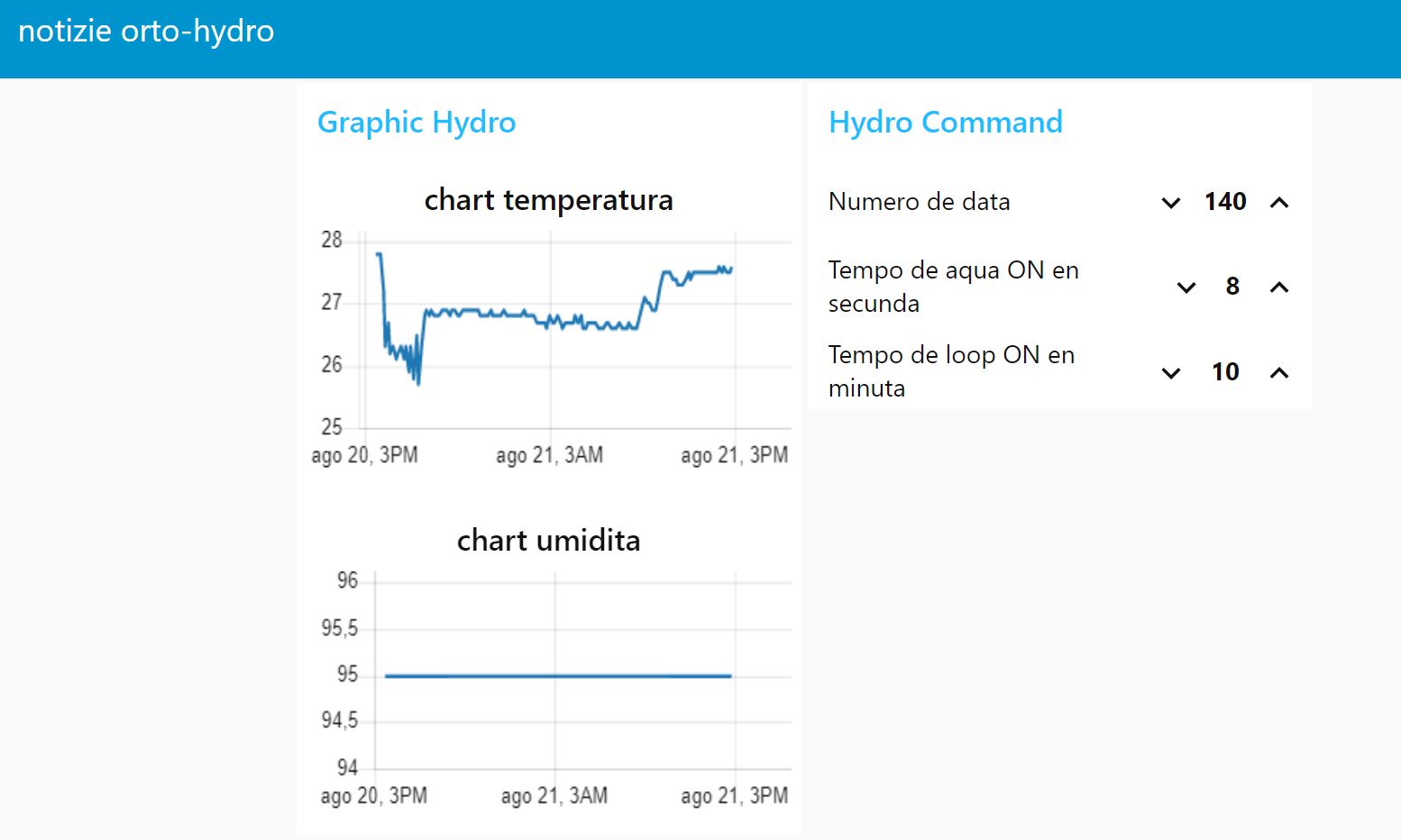
Interface of the hydroponic system
The interface shows the measurement on temperature and humidity on the left part and the command on the right part.
- “numero de data” : shows the number of the last data measured
- “Tempo de aqua en secunda” : choose the timing on which the water pump is ON when water level sensor detect lack of water
- “Tempo de loop ON en minuta” : Choose the timing in minute for each measurement from DHT11 sensor and water level sensor
Install a database and PHPMyAdmin on the raspi
- install apache2 server
sudo apt-get install apache2
- install php
sudo apt-get install php libapache2-mod-php
- install mariaDB
sudo apt-get install mariadb-server
- install phpmyadmin
sudo apt-get install phpmyadmin
- on blue install screen, select apache2
- “yes” to configure phpmyadmin and select root password (we’ve choosen “test” here)
- change apache conf to access phpmyadmin, in /etc/apache2/apache2.conf add at the end
Note
at this point login/pass to phpmyadmin is “root”/”test”
Include /etc/phpmyadmin/apache.conf
Configure the dataBase on PHPmyadmin
- create database on phpmyadmin, dedicated to hydro system “DB_OrtoHydro”
- create table for temperature & humidity to be stored
- use function in nodered to store date recieved from broker before storing to database (context.store & context.get function in “DB Filter”)
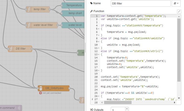
function to store MQTT variable and send SQL command to database
retrieve data from DB via NodeRed and display it on chart line
inject response from DB to graphic doesn’t work like that, needs to inject a n array with a predefined format https://github.com/node-red/node-red-dashboard/blob/master/Charts.md#line-charts-1 issues with date format, changed it in phpmyadmin from timestamp to date time so there are no issue with time zone
Configuration of the Arduino MKR1000 code
The code used has been commented to explain each library call, each function or variable.
Warning
To compile correctly the code, its needed to install the following library through Adruino IDE
- “WiFi” to allow Arduino MKR to use wifi function
- “Adafruit Unified Sensor” & “DHT sensor library” to use DHT sensor
- “EspMQTTClient” & “PubSubClient” to use MSQTT functions
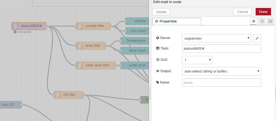
On NodeRed, retrieve value via mqtt input, and retrieve all topic published on stationMKR via “stationMKR/#” for topic
Arrange NodeRed User interface
Note
Send message on a topic to send command to Arduino, don’t forget to subscribe to same topic on arduino side
Warning
The code comport some section commented which are about sleeping mode, this would allow the arduino to turn OFF and turn ON on a choosen period of time. The sleeping mode hasn’t been integrated because it leads to some unknown issue on posting and reading via MSQTT channels. The code has been left for future evolution.
Note
Remarks & Observations on sleepmode usage:
- The alarm time is doubled, i don’t understand why yet, when set up to 30 minute, it goes to 1h OFF (in the code above)
- You can’t upload program if its in the current sleep mode, there is a 5 secondes delay at the beginning of the loop but you can put the Arduino in “fimware” mode by pressing “reset” button twice. (the L LED shall be blinking). you’ll have to re-select the correct output/COM for the Arduino
System and part design
In this part will be documented the design created to build this system
Water level sensor
1rst model of the sensor, 3D print to support the water level sensor and the DHT11 sensor
The first model of the waterlever sensor used
File for the water level sensor that fit in seed grower
File for the air temp&humidity sensor that fit water level support
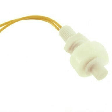
This solution has been abandoned because this kind of water level sensor is used for big tank of liquid.
Indeed, the minimum height of water that can be detected is of about 25mm.
This can’t be applied with the seed grower module because the waterlevel needs to be lower, otherwise too much water can leads to moistures.
2nd model, detection of the waterlevel with water conductivity
The second solution is to use water conductivity between 2 metallic pins connected to arduino.

top of the support with graduation every 5 mm to setup distance between the 2 mettalic pins

The 2 mettalic pins at the bottom of the water level sensor
inside of the waterlevel sensor
outside of the waterlevel sensor
Note
to use water conductivity we use the alimentation of the water pump. If current is always ON, this lead to electrolyse around mettalic pins. The code in Arduino needs to prevent long period of current in the water
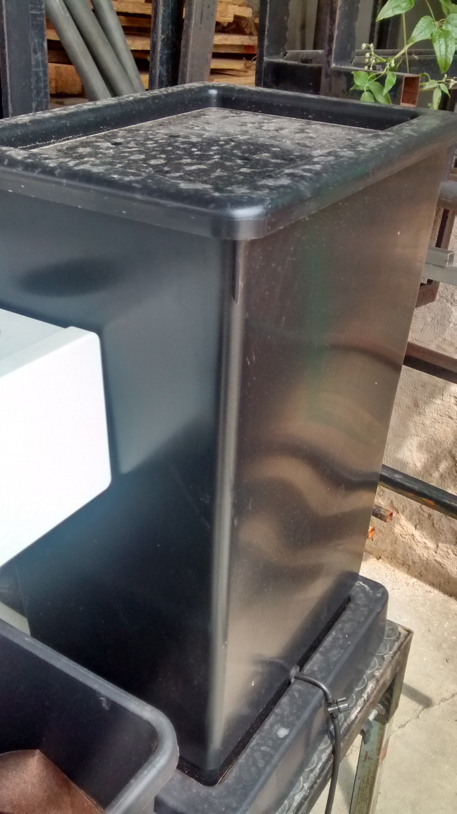
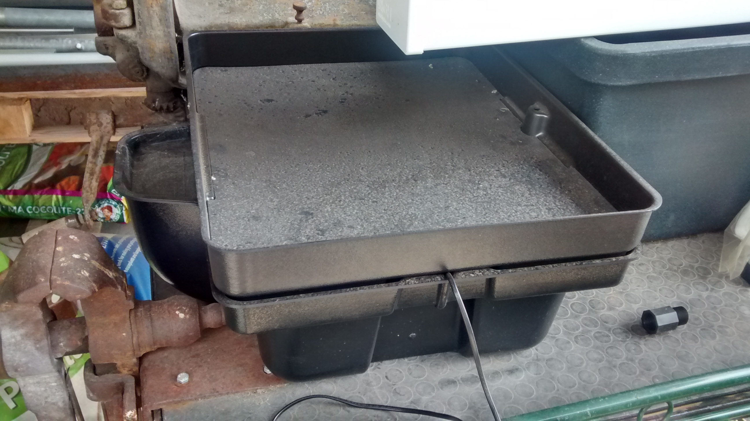
Design of the support Box
To support the seed box, the building process was choosen to use plywood cut by laser to be mounted after. Plexy could be used but its complicated to glue it after and its more expensive
1rst model, good dimention but not water proof
The first model could fit the seed box on top with a potential water tank at the bottom, but desperate try out to make a plywood box waterproof failed miserably (basically stick plastic to each face and use glue gun on each junction)
2nd model, support seed box and integrate basic water box
On the 2nd design, it has been choosen to make a support that contain the seed box, and at the bottom the possibility to put a basic recipient that is waterproof. The design of the 2nd box has been a bit tricky, the design and reflexion on the support has been led on sketchup. Exporting to dxf from sketchup isn’t possible with the free version. Also to have thumb that could be used for easy mounting of the box we used openscad with laser cut box module.
So the process to have files that could be used for the laser cut is the following:
- From sketchup, Export each element into a STL (The sketchup model doesn’t have thumbs)
- Import STL into FREECAD, remodel each element, and export the face as DXF
- Generate box with same size with OPENSCAD to have thumbs with correct dimension
- Export from OPENSCAD the DXF faces of the generated boxe
- In Inkscape, import DXF from each element from FREECAD and face from boxes generated from OPENSCAD
- Assemble everything to have the element in SVG with correct thumbs size
- import everything in laser software to be able to build everything
Usages
| S: R P: C N: 1 | S: C P: C N: 3 | S: C P: C N: 3 | S: C P: C N: 5 | S: R P: S N: 1 | S: R P: S N: 1 |
|---|---|---|---|---|---|
| S: R P: C N: 1 | S: C P: P N: 1 | S: C P: C N: 3 | S: C P: C N: 5 | S: R P: S N: 1 | S: R P: S N: 1 |
| S: R P: C N: 1 | S: C P: P N: 2 | S: C P: C N: 1 | S: C P: C N: 5 | S: R P: S N: 1 | S: R P: S N: 1 |
| S: R P: C N: 8 | S: C P: P N: 2 | S: C P: S N: 1 | S: C P: S N: 1 | S: R P: S N: 1 | S: R P: S N: 1 |
| S: R P: C N: 5 | S: C P: P N: 1 | S: C P: S N: 1 | S: C P: S N: 1 | S: R P: S N: 10 | S: R P: S N: 10 |
| S: R P: C N: 10 | S: C P: P N: 1 | S: C P: S N: 10 | S: C P: S N: 10 | S: R P: S N: 10 | S: R P: S N: 10 |
| S: R P: C N: 20 | S: C P: P N: 1 | S: C P: S N: 10 | S: C P: S N: 10 | S: R P: B N: 1 | S: R P: B N: 1 |
| S: R P: C N: 1 | S: R P: P N: 1 | S: C P: B N: 1 | S: C P: B N: 1 | S: R P: B N: 1 | S: R P: B N: 1 |
| S: R P: P N: 1 | S: R P: P N: 1 | S: C P: B N: 1 | S: C P: B N: 1 | S: R P: B N: 1 | S: R P: B N: 1 |
| S: R P: P N: 2 | S: R P: P N: 1 | S: C P: B N: 1 | S: C P: B N: 1 | S: R P: B N: 1 | Water Level Sensor |
Legend
- S : Subtrat used, R for rockwool, C for coconut
- P : Plant seed choosen, C for carrt, P for pepper, B for bean, S for salad
- N : number of seeds
Footnotes
| [1] | https://www.youtube.com/watch?v=EIxdz-2rhLs |
| [2] | https://www.youtube.com/watch?v=FU6Henjf_Qs |
| [3] | https://www.youtube.com/watch?v=ubqzvbox5dc |
| [4] | https://thekurks.net/blog/2018/1/24/guide-to-arduino-sleep-mode |
| [5] | http://forcetronic.blogspot.com/2016/09/reducing-power-consumption-on-arduino_24.html |
| [6] | https://create.arduino.cc/projecthub/Pedro52/arduino-esp32-diy-water-level-sensor-and-diy-level-indicator-3d513d |
| [7] | https://hsbp.org/hack2o |